All Wound Up About EFHW Transformer Winding
- Dan Koellen AI6XG

- Feb 27, 2023
- 5 min read
After successfully using an End Fed Half Wave (EFHW) antenna for SOTA, I decided to build a 10 to 80 meter EFHW antenna for my home station. Several EFHW 'how to' sources have advocated using a twisted primary winding with a crossover secondary winding, but I have not found data or explanation why this configuration is preferred. I evaluated three winding configurations by measuring transformer loss of each configuration to determine the preferred configuration for my transformer.
The Experiment
Fair-rite FT240-43 cores, procured through an authorized Fair-rite distributor, were used for the experiment. Evaluating my needs for the home station EFHW with respect to power handling, mode and outdoor temperatures; I decided to use two stacked FT240-43 cores for my transformer. Turn ratios were considered for broadband performance across 80 to 10 meters, after evaluation I decided to use 2:14 primary to secondary turns ratio.
Three winding configurations were evaluated for transformer efficiency/loss using one transformer and a 2400 ohm load resistor method documented in a prior post. A nanoVNA-F, manufactured by BH5HNU, hw version 3.1 using fw version 0.2.1 was used for the measurements. The three winding configurations were the popular twisted primary with a crossover secondary, twisted primary with no crossover on a tightly wound secondary, and a tapped single tightly wound coil. Enamel covered #16 wire was used for the windings.
Heat distribution or other characteristics were not evaluated.
Figure 1 L to R Twisted Primary w/ Crossover, Twisted Primary w/ No Crossover, Tapped Single Winding
Conclusions
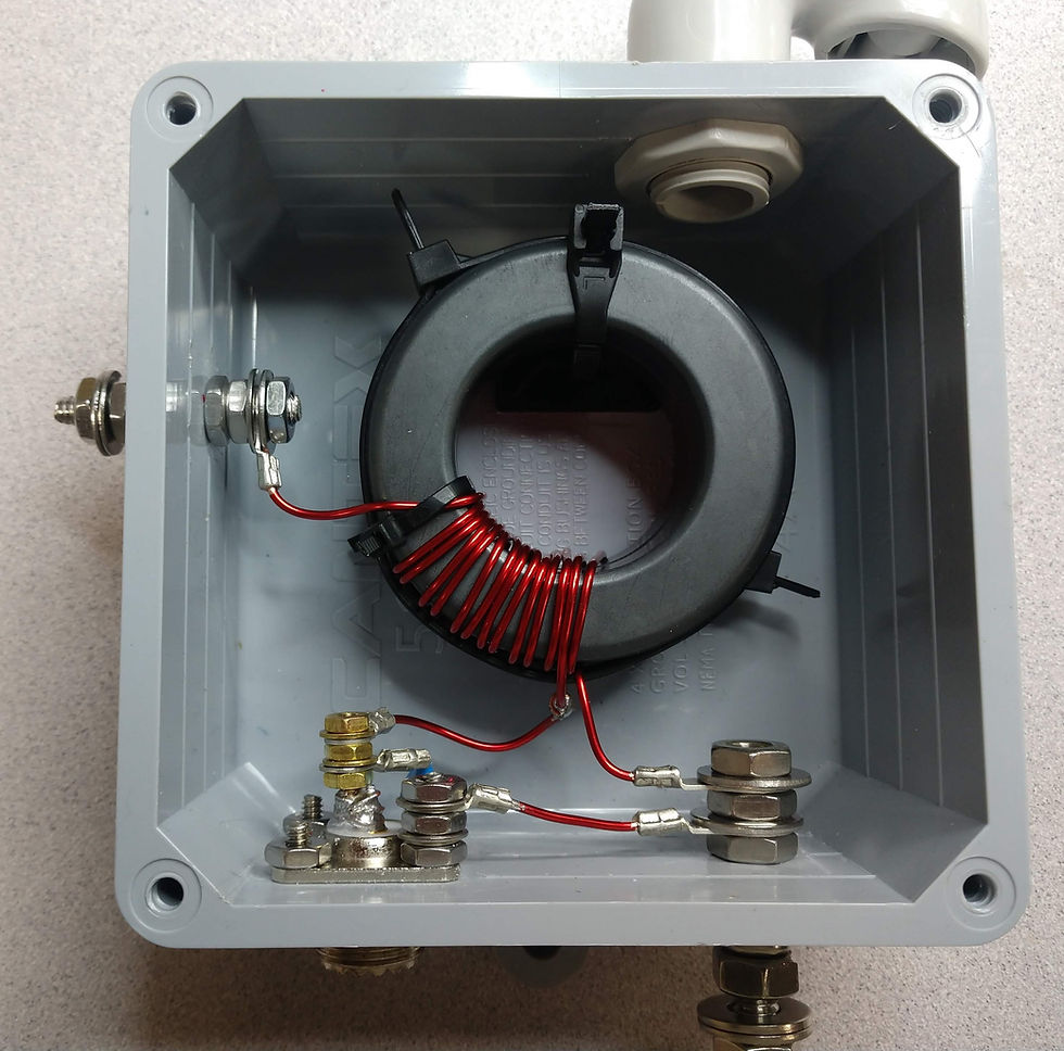
Keep it simple, a single tapped tightly wound winding has the least transformer loss. And it is easier to wind as I experienced in my EFHW transformer shown below.
The greater losses are in the upper bands: the now fun bands with the sun's increasing sunspot activity.
Crossover winding losses likely due to increased Rs power loss
Twisted primary winding losses are due to coupling coefficient and winding capacitance effects
Tightly wound windings will improve transformer efficiency
Transformer Loss Data
Transformer Loss was measured from 80 to 10 meters and shown below. Measurements were made with and without a 100 pF primary capacitor at low power using the NanoVNA.

Figure 3 Transformer Loss Data for All Three Winding Configurations
BF_XO is Twisted Primary w/ Crossover on Secondary Winding
BF_NoXO is Twisted Primary w/ No Crossover on Secondary Winding
tapped is Tapped Single Winding
The data shows little difference in the low bands but diverges as frequency increases. Overall the popular Twisted Primary with Crossover Secondary has the most loss, especially at frequencies above 20 meters. The Tapped Single Winding has the least loss across the HF Ham Bands. The transformer with No Crossover is in between.
Discussion
After measuring transformer loss for the different winding configurations, the cores were used for the antenna install. No further measurements, such as coupling coefficient, were made. But we can look closer at the data and differences between the configurations to gleam possible explanation of the differences measured.
Elimination of the Crossover Winding
We can look at the difference in transformer losses for the two configurations that both have a twisted primary but differ in secondary winding configuration.
Figure 4 Transformers with Twisted Primary Windings but Different Secondary Winding Configuration
Below shows the delta in transformer loss for these two configurations.
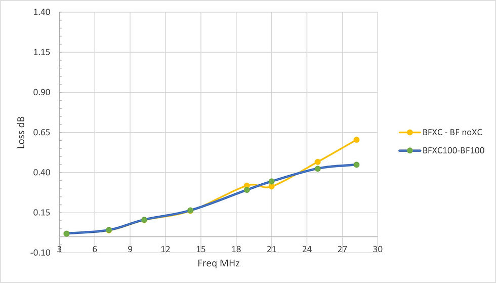
Figure 5 Transformer Loss Delta
BF_XO is Twisted Primary w/ Crossover on Secondary Winding
BF_NoXO is Twisted Primary w/ No Crossover on Secondary Winding
The difference in transformer loss increase with frequency is more rapid for frequencies above 40 meters or about 7 MHz. The physical difference between the two winding configurations is predominantly the length of core that the secondary winding covers. The lower loss configuration - no crossover- has much less coverage of the core. Power loss through the ferrite may explain the difference.
The permeability of the -43 mix ferrite is dependent on frequency and is also complex as shown in figure 6 left. Being complex there is an reactive (imaginary) component and a resistive (real) component. Resistive losses will be dissipation by heat while reactive loss is not power dissipative.
Figure 6 Left -43 Permeability vs. Frequency (1) Figure 6 Right -43 Resistive Rs and Reactive Xs
As you can see from figure 6 right, the real component Rs starts to dominate at ~7 MHz, similar to the transform loss delta data in figure 5. Likely heating of the core is the loss mechanism for the crossover secondary windings.
Elimination of the Twisted Primary Winding
Let us now look at the difference in transformer losses for the two configurations that have tightly wound secondary windings but differ in primary winding configuration.
Figure 7 Transformers with Twisted and Tapped Primary Windings
The chart below shows the delta in transformer loss for these two configurations. The difference in loss is essentially zero until 17 meters where it rapidly increases with frequency.
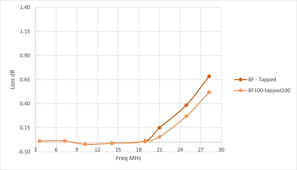
Figure 8 Transformer Loss Delta
BF is Twisted Primary w/ No Crossover on Secondary Winding
Tapped is Tapped Single Winding
The physical difference between the two winding configurations is a twisted primary versus a tapped single winding as the primary. One would expect that a difference in coupling coefficient would contribute to the transformer loss delta seen in figure 8. The twisted primary winding over the secondary winding is assumed to have a lower coupling coefficient than the tapped winding. But, does a difference in coupling coefficient explain the behavior seen in figure 8?
To test this hypothesis, a SimNEC circuit was built with an autotransformer block representing the tapped winding configuration and a coupled transformer representing the twisted pair configuration. The coupling coefficient may be independently assigned. The coupling coefficient, k, is defined as:
k = (1-Ll/Lm)^0.5 equation 1
Where Lm is the magnetizing inductance and Ll is the leakage inductance. Ll may be measured or estimated for a transformer and Lm may be measured or calculated using fundamental properties of the core and windings. It has been shown that Ll is fairly constant over HF range but k will be frequency dependent since Lm is frequency dependent (2).
In the SimNEC circuit, the leakage inductance was estimated and magnetizing inductance was calculated.
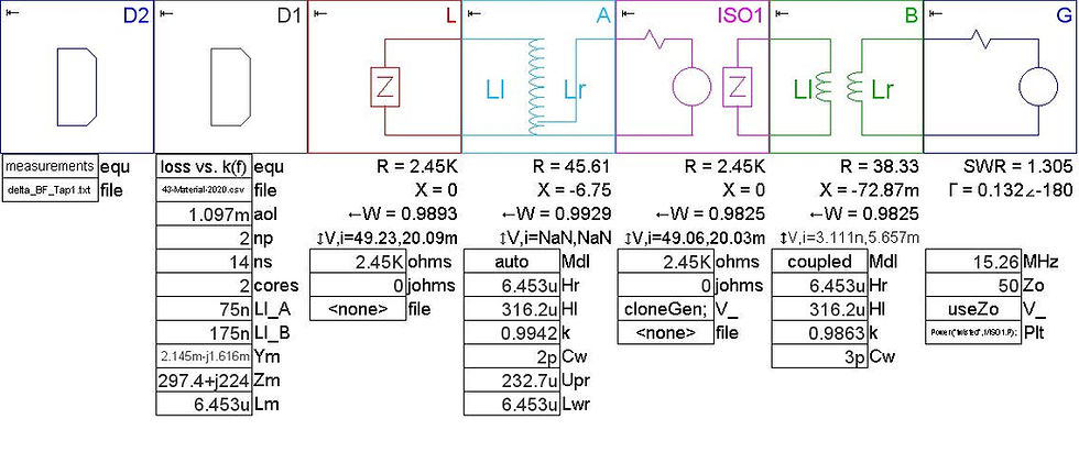
Figure 9 SimNEC Circuit Built to Compare Tapped and Twisted Primaries
Block D1 is used to calculate Lm and to input transformer parameters including Ll estimates. Blocks A and B are the tapped and twisted primaries respectively. The transformer loss was calculated for both transformer configurations, as was the difference (delta) in loss. The measured loss delta from figure 8 was also plotted against the SimNEC model. The comparison plot is shown below.
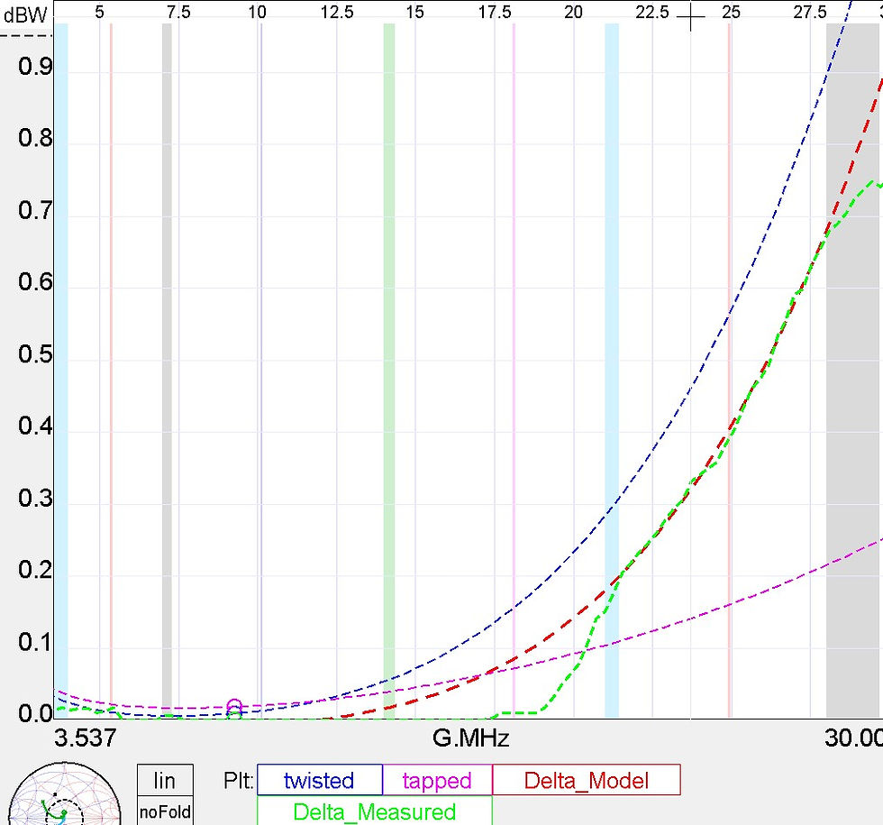
Figure 10 Plot Comparison of Transformer Loss and Delta
In figure 10, the difference (delta) of transformer loss between the two configurations is the red dashed line. The measured delta data, figure 8, is the green dashed line. As you can see, the agreement is fairly good. To provide this fit, reasonable estimates of leakage inductance were made to provide coupling coefficients between 0.99 to 0.98. As hypothesized, the coupling coefficient of the twisted primary was less than that of the tapped primary. But surprisingly, the coefficients are closer in value than I thought they would be. The other parameter that significantly affected transformer loss was Cw, the winding capacitance. In this model, the twisted primary had a higher winding capacitance than the tapped winding. This is reasonable considering the construction of the windings.
Transformer Loss and Winding Tightness
In performing transformer loss measurements I noticed that the tightness of the windings had an effect on transformer loss. To test this I wound a tapped transformer with #24 wire rather than #16 wire that was used for the previous measurement. The physically smaller size of the #24 wire permitted much closer windings than #16 wire using the same two FT240-43 cores. The chart below shows that transformer loss was less for the closer wound #24 wire windings.

References
Fair-Rite Corporation Supplied Data
Owen Duffy "A Simple Simsmith Model for Exploration of a Common EFHW Transformer Design – 2t:14t"


Comments