Toroid Transformers - How Hot Will It Get?
- Dan Koellen AI6XG
- Mar 1, 2022
- 11 min read
Updated: Apr 9, 2022
There are a number of factors in choosing a toroid for a RF transformer. While one may model electrical performance, calculate predicted efficiency and frequency response among other characteristics; predicting the power handling capability of a particular core is not as straightforward. A common question when building a transformer is what size core do I need?
I will look at a couple methods that have been used and reported, discuss the merits and the shortcomings of the methods. This is a summary of my research and observations, there is likely more information available. I welcome constructive comments and pointers that will improve this overview.
Amidon Magnetic Flux Density
Amidon published in their tech data book (pages 1-35, 36, 38) a discussion about magnetic flux density (denoted by B) and its relationship to core heating. They state that there are two contributors to transformer heating: wire heat and core heat. Wire heating is due to both AC and DC signal components while core heat is due to AC component only. It continues to state that a core will first be affected by core loss induced heating well before magnetic saturation occurs for both iron powder and ferrite cores. The core heating is stated to be dependent on B - magnetic flux density - and frequency; the table below provides what they have determined to be maximum flux density versus frequency.

There is no explanation by Amidon whether Bmax was calculated or experimentally derived. Though charting the Amidon Bmax table shows that Bmax has an inverse square root relationship with frequency.

To calculate magnetic flux density for an application the following equation was provided indicating that magnetic flux density is inversely proportional to number of turns, cross-sectional area and frequency and proportional to voltage across the transformer.

For a given toroid and frequency, increasing the number of turns will decrease magnetic flux density while increasing voltage will increase the magnetic flux density. This approach suggests a maximum limit for operation but does not provide predicted temperature rise.
A major concern about this method is that it does not comprehend differences in mix or core material. Ferrite and iron powder cores are treated the same, as are different mixes. This casts doubt on the usefulness of this method as shown in an example by Owen Duffy. In spite of this shortcoming, a later example will show that this method may be useful under certain circumstances.
Ferrite Transformer Loss
For ferrite core toroids, transformer loss may be used to predict the power dissipated in the core. Transformer loss is insertion loss minus mismatch loss, which is predominately core loss. This is covered in-depth by Owen Duffy and others so I will not go into detail on how to determine transformer loss.
To use this approach you need to know how much power is being delivered to the core, then you use transformer effeciency to predict the portion of that power that will dissipated by the core.
Predicting core loss by calculation will work for ferrite cores but not for iron powder cores. Ferrite cores have complex relative permeability consisting of u' (real) and u" (imaginary). Though it may seem counterintuitive, the imaginary part, u", of the relative permeability determines the resistive losses of the core while the real part, u', determines the core's reactance - which is lossless. For iron powder cores u" = 0 so theoretically there is no core loss, so power dissipated in the core can not be calculated using this method.
Predicting Core Heat Performance
Amidon
To use the Amidon method you need to know the voltage across the core windings. If you know the power (P) into the transformer and the impedance (Z) then the voltage (V) can be calculated using:
P = V^2/Z Equation 2
For voltage across a shunt you need to convert the impedance to admittance (Y) and use the real part, the conductance (G), to determine voltage:
P = V^2 * G rearranging to get V = sqrt[(P/G)] Equation 3
If the impedance (admittance) is real only then the equation reverts to the familiar V = sqrt[(P*R)]
Then you can use the calculated voltage to determine the magnetic flux density magnitude. If you only know SWR then you will have to use the worst case of all real impedance where R = SWR * 50 ohms. Remember that with complex Z there are many values of Z that will give a particular SWR, the largest magnetic field density will be with imaginary portion of Z equal to zero. In this case, a transformer with a SWR of 2 would have R = 2 * 50 = 100 ohms. For example, for a rig that sees a SWR of 3 and is delivering 5 watts of power to a transformer primary, the maximum voltage across the core primary windings will be V = sqrt[(5 * 150)] = 27.4 Volts.
With this method you will only get an indication of whether you are below or above Bmax.
Transformer Loss
The Transformer loss method predicts the power dissipated in a core. To use this method you need to either calculate the transformer efficiency or measure core loss directly. If you have measured transformer loss in dB (TL) then transformer efficiency (TE) will be:
TE = 10^(-1*TL/10) Equation 4
To determine power dissipated (Pd) in the core simply use the power applied (Pa):
Pd = (1 - TE) * Pa or if TE is a percentage Pd = (1 - TE/100) * Pa Equation 5
How Hot?
We can attempt to predict the rise in temperature for a core using the power dissipated by the core as predicted by transformer loss. However there are several variables that will influence temperature rise: size of core, surface area to volume ratio, air flow (or lack of), applied power duty cycle, and assumptions made during temperature estimation. Also the maximum temperature that the core may operate at will vary according to mix. That temperature, referred to as Tc - the Curie temperature, is only ~135C for the popular -43 mix. Other mixes have higher Curie temperatures: mix -61 Tc >= 350C and mix -52 Tc >= 250C.
Amidon suggests that the following equation may be used to calculate temperature rise for a given power dissipation:

Amidon again does not provide the source for this equation, whether it is empirically or theoretically derived.
On the other hand Owen Duffy suggests using a methodology for designing heat sinks, where long term open air temperature rise will be:
~10K/Pd/SA with 10 degrees K, Pd power dissipated in watts and SA surface area in meters^2
He states that this is very conservative and the ferrite emissivity may be up to 5 times better, I use an 'emissivity factor' with an inclusive range of 1 to 5 to factor in surface area to volume ratio as well. Generally smaller toroids will have a greater surface area to volume ratio so heat will be dissipated more effectively. For surface area in cm^2 and emissivity factor EF [1,5] we get TR - temperature rise (C):
TR = 1000*Pd/(SA(cm^2)/EF Equation 7
Now you have two ways to calculate temperature rise for a given power dissipated by the core. These equations assume open air and 100% duty cycle.
A Few Examples
The prior discussion showed a couple approaches to predicting temperature rise. And within these approaches there are assumptions and estimates that are made so predicting actual temperature rise is difficult and can involve a few educated guesses. The following examples will provide some guidance with actual use examples. They are not fully quantitative but will give guidance on how to approach determining whether your core will operate in a safe temperature range. Beware that overheated ferrite cores can explode if overheated, so it is better to be safe.
Low Power EFHW for SOTA
For SOTA operation I use a trapped end fed half wave (EFHW) antenna with a FT50-43 toroid core transformer to match the EFHW high impedance to 50 Ohms. The transformer has a primary winding of 3 turns, this is a popular configuration for use with low power antennas and this core. I routinely feed 5 watts into this antenna and on occasions will go as high as 10 watts. The transformer is mounted in free air on the back of connector and encapsulated in epoxy. Through my two years of use on several summits, in direct sunlight and warm temperatures, I have not had an issue with overheating or becoming warm to the touch. Let's see if this follows with the methods covered here by looking at calculations in the 40 meter ham band for each method:

If you were designing this configuration using Amidon maximum magnetic flux density, a FT50-43 toroid would be deemed too small. Using this method Bmax is 59 gauss while the smallest B is 128 gauss at 1:1 SWR as seen at the top row of the calculation table. If we use transformer loss to calculate temperature rise we can see the Duffy method at 33% duty cycle with maximum emissivity provides a more reasonable value of 20C temperature rise at a 1:1 SWR. If the emissivity factor is lowered then the temperature rise will increase proportionally using the Duffy method. A emissivity factor of 5 is reasonable for this toroid since the surface area to volume ratio (11.3/cm) is much higher than for larger cores.
From this analysis, one would guess that my duty cycle is less than 33% on CW SOTA exchanges. And that digital modes with high duty cycle would not be recommended for this transformer.
WSPR Testing
Another SOTA enthusiast, Mike KN6EZE, decided to use Weak Signal Propagation Reporter (WSPR) to test operating efficiency for EFHW matching transformers made with a FT50-43 core versus a Fair-rite 2643625002 core. The Fair-rite 2643625002 core is also -43 mix but a slightly larger diameter and much thicker toroid than the FT50.

Like the previous example, both transformers had a primary winding of 3 turns and provided a low SWR match to the antenna. WSPR testing was run on 40 meters with consecutive transmissions of 2 watts. WSPR transmissions are nearly 100% duty cycle. During testing Mike noticed that the FT50-43 transformer got quite warm as the transmissions continued while the Fair-rite 2643625002 transformer remained cool. Could we have predicted this using the methods discussed earlier?
First, let's look at the transformer efficiency for each type of transformer as measured by this author.

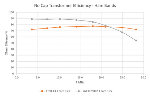


Chart 3 - Transformer Efficiency (%) Chart 4 - Transformer Loss (dB)
The larger core has better transformer efficiency at 40 meters than the FT50-43, ~89% vs. ~74%. And since the Fair-rite 2643625002 toroid is larger than the FT50-43 we would expect even better power dissipating capability as well. Do the calculations show this?


For the Fair-rite 2643625002 transformer all methods point to safe operation at 2 watts even with 100% duty cycle. While the power dissipated by this core is less due to better efficiency, the size of this core also provides an advantage by dissipating more heat as seen in the 100% Amidon and Duffy calculations. There is 1/3 of the power to dissipate but the temperature rise is much less than 1/3 of the FT50-43 transformer. This is due to the larger size of the core. I chose to use an emissivity factor 3 for this toroid due to the smaller surface area to volume ratio, a larger emissivity value would further decrease predicted temperature rise.
For the FT50-43 transformer all methods would indicate operation at 2 watts and 100% duty cycle is not recommended. But which method predicts the temperature rise best? The Amidon method would produce a very hot transformer with a 53C temperature rise over ambient. The Duffy method estimates a 24C temperature rise over ambient which would produce a very warm transformer, a better prediction of actual operation. Of course, this is assuming an emissivity factor of 5, lower values would increase the temperature rise.
EFHW Operation on the Wrong Band
Another SOTA operator was using an EFHW with a FT50-43 transformer with a primary winding of 3 turns. The EFHW was cut for 40 meters with harmonic operation on 20 meters. The EFHW was matched well at 40 meters with a low SWR, the transformer worked well with no significant heating noticed. The operator decided to try operation at 30 meters and low power but a high SWR in excess of 6:1 was encountered. A tuning unit in the transceiver was successful in reducing the SWR as seen by the transmitter finals but the high SWR still existed at the transformer. After an attempt at operation it was noticed that the tuner had to be readjusted and that the transformer got hot to the touch.
I don't have the impedance measurements to pinpoint what was causing the temperature rise. But I would guess that the following occurred:
The ATU was not able to provide a conjugate impedance match to the transformer
The ATU provided adequate match to the transmitter, protecting the transmitter finals
The impedance at the transformer causing the high SWR had a significant real component so that the voltage across the transformer primary was significantly high.
This would increase the magnetic flux density across the primary to be much greater than Bmax. This is plausible since we see from chart 7 below that low SWR operation at 5 watts on 30 meters already violates Bmax significantly. Also we know this transformer configuration operated well at 40 meters and low SWR and chart 3 shows that the transformer efficiency is very similar for 40 and 30 meters. That leads to the conclusion that magnetic flux density had a higher impact in this case than transformer efficiency.

Example Summary
In these examples we saw that we can predict the temperature rise of a transformer but one has to know which method to use. We saw that in well matched cases, the transformer loss method of finding power dissipation will provide a reasonable estimation. Predicting the temperature rise from the power dissipated has more variables. Using the heat sink derived approach of Owen Duffy requires you to estimate duty cycle and emissivity factor which will have a significant impact on the predicted values. And deciding on toroid size and shape will depend also on surface area to volume ratio which is not constant between different toroids, this ratio will affect the emissivity factor.
In cases of large mismatch as seen in the third example, the maximum magnetic flux density method of Amidon may better explain temperature rise that occurs. Impedance measurements rather than SWR measurements give a better prediction of magnetic flux density. Duty cycle affects each approach as well.
Conclusions
There is no one approach that will accurately and quantitatively predict temperature rise. Use each approach while testing different assumptions and estimates. Then build it and see if it works.
Each approach, transformer loss and magnetic flux density, has cases in which they better apply.
There is not just one approach that is appropriate, though Amidon B max method's lack of core material and mix distinction detracts from its utility.
Temperature rise is difficult to predict accurately
Temperature rise trends may be predicted
Many factors have an influence, some that you have to approximate
emissivity factor
duty cycle
transformer efficiency
air flow/enclosure
core physical characteristics
For QRP digital modes, WSPR or QRP+, the Fair-rite 2643625002 toroid is recommended for EFHW transformers over the FT50-43 toroid
Mixes with higher Tc - Curie temperature - can tolerate greater temperature rise
Appendix
Calculation Chart Explanation
The charts presented in this post came from an excel spreadsheet that calculated various transformer values using equations presented in the post.

Parameter A is the maximum allowable magnetic flux calculated for a transformer per equation 1
Parameter B is magnetic flux densities predicted at 1:1, 2:1, 3:1 SWRs with no reactive component per equation 1
Parameter C is power to be dissipated calculated per equations 3 and 5
Parameter D is predicted temperature rise for parameter C power using equation 6, the Amidon method. The left column is for 100% duty cycle and the right column for 33% duty cycle
Parameter E is predicted temperature rise for parameter C power using equation 7, the heat sink approach. The left column is for 100% duty cycle and the right column for 33% duty cycle.
Parameter F is the emissivity value used for parameter E
Parameter G is the surface area of the toroid
Parameter H is the surface area to volume ratio of the toroid
Converting Impedance to Admittance
Impedance is a complex value (a + jb) that consists of real (a) and imaginary (b) parts where j^2 = -1. Admittance is the reciprocal of impedance, for a complex number a reciprocal calculation is not as easy as for a real number but still straightforward.
The reciprocal of a complex number is the complex conjugate divided by the magnitude squared. That is:
for a + jb --> 1/(a + jb) = (a - jb)/(a^2 + b^2)
Conductance G is the real part of admittance Y which is the reciprocal of the impedance Z,
so for Z = a + jb, G = a/(a^2 + b^2)