QRP Tube: High Voltage DC to DC Supply Evaluation
- Dan Koellen AI6XG

- May 1, 2023
- 6 min read
Updated: Jan 27, 2025
The high voltage supply for the vacuum tube transmitter needs to be low noise in the 40 meter band, efficient for battery operation and able to supply at least 200 Vdc from a 12 volt battery. The current draw is expected to be about 50 mA, a supply with at least 75 mA capability would be preferred. I expected that the load on the supply would change during keying of the transmitter. This means the supply needs to maintain a steady output voltage under changing loads for a clean CW signal. A means to enable and disable the supply would be preferred as well. The supply could be designed and built or purchased as an off the shelf item.
This post is part of the series about a backpackable vacuum tube based transmitter teamed with a QCX receiver for portable SOTA activation. Other posts are the overview, concept and results, and detailed descriptions of the tube transmitter and QCX interfacing, modification and antenna switching.
The Search
A number of off the shelf DC to DC high voltage supplies stocked by the major distributors were evaluated. Most were very expensive, too large or were not in stock and with long lead times. I discovered that Nixie tube enthusiasts were also using DC to DC switching mode power supplies (SMPS) in the 180 Vdc range. Nixie tube forums had extensive discussion about high voltage supplies. To build an efficient and low noise SMPS requires detailed engineering in the circuit design and layout. An excellent source of design insight is on Nick de Smith's website, particularly his Nixie HV Switching PSU post.
The off the shelf SMPS used by many Nixie tube enthusiasts are lower current than my needs and often limited to 180 Vdc output. Further searching I found a family of SMPS that met the voltage and current needs, had a enable/disable pin, was readily available, and reasonably priced. The supplies are the NCH6300HV family by OMNIXIE. The designers had not measured the noise content of their supply. The design of the supply looked solid so I decided to to test for noise and voltage stability.
NCH6300HV Evaluation
The NCH6300HV module was evaluated, the technical specifications are shown below:


Characteristics Evaluated
All evaluations were performed using a 12Vdc 3Ahr LiFePo battery, the battery was fully charged at the start of testing. Two versions were evaluated, the NCH6300HV and a prototype NCH6301HV. The NCH6301HV can provide higher current than the NCH6300HV, but its output voltage is fixed unlike the NCH6300HV. The following were evaluated:
Efficiency
Output Voltage Stability vs. Battery Voltage as the battery discharges, ~80 mA was being drawn from the high voltage output.
Output Voltage Stability vs. Changing Load
Listening for birdies and other noise in the 40 meter band using a KX2 with an antenna near the power supply
Forty meter spectra comparison from SDRplay receiver with antenna adjacent to power supply operating under different modes
Turn on time and integrity using the enable mode
Results
The results of the testing were very good and meet the requirements to use for the vacuum tube transmitter's high voltage supply. In the final setup, the NE6300HV module is successfully used to provide the high voltage need for transmitter operation.
The efficiency was measured to be 81%, lower than expected but still adequate
The output voltage varied less than 1% from a fully charged to discharged battery. The output voltage stabilizes to a constant value after initial battery discharge.
The output voltage varied less than 0.3% with a rapid load current increase of over 120%
No birdies or other RF noise was detected by listening or spectra comparison
Enable has an acceptable delay to output voltage
Testing Data
Efficiency and Enable/Disable Test
The NCH6300HV module was powered by a 12 Vdc 3 AHr LiFePo4 battery and loaded with a 2 kOhm 20 Watt resistor. Measurements were made with the module enabled or disabled using the SHDN pin. The output voltage was set to ~180 Vdc.

The efficiency was found to be lower than expected but still adequate for use with the Tube Transmitter.
The SHDN pin was found to work well to enable or disable the module. Note that even with the SMPS module disabled there is still Vout of approximately one diode drop below Vin. There is also current drawn by the module when disabled, assuming to be current through the load.
The output voltage is available within 0.3 seconds from SHDN pin pulled high, with the output voltage ramping at about 1100 V/sec. This is acceptable operation if the supply will not have to be disabled during receive due to generated noise or RFI. In the final application the supply was left running during receive.
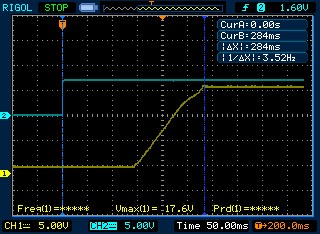
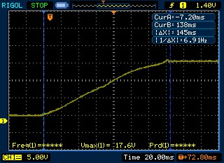
Blue Trace: SHDN pin Yellow Trace: Vout (10x probe)
Output Voltage Stability
The NCH6300HV module was powered by a 12 Vdc 3 AHr LiFePo4 battery and loaded with a 2.1 kOhm 20 Watt resistor. As the module was being prepared for long term testing it failed. Operation at Vout = 180 Vdc and Iout = 90 mA is permitted for short durations but is not viable for long durations. The test conditions were beyond the specified limit for the module so were not appropriate. A NCH6301HV module was provided to me to test long term output voltage stability, this module was designed to operated at this load for a long duration. As it turns out, the actual use conditions in the Tube Transmitter are at a lower load current and for shorter (CW) durations. Ultimately the NCH6300HV module was used for the Tube Transmitter with no problem. Testing for output voltage stability used the NCH6301HV module since it was designed to operate within the test conditions.

When tested for varying input voltage (Vbatt) the module's output voltage (HV) stayed consistent. The output voltage only changed by -0.28% for a -3.1% change in input voltage. This test was run with a 2100 Ohm load.

When tested for long duration operation, the output voltage (HV) drooped initially and then settled to a consistent voltage even as the input voltage (Vbatt) continued to drop. This test was performed for 1 hour. This test was run with a 2100 Ohm load.


The test was repeated while letting the battery deplete, this occurred after about 2 hours of continuous operation with a 2100 Ohm load. The same behavior of the output voltage (HV) settling to a consistent voltage was observed.
The output voltage stability was also tested with changing loads to replicate CW keying of the transmitter. The following array of power resistors was set up, the output of the module was connected across the array. The output and input voltages were monitored as loading was changed by shorting out various resistors. The module was powered by a 12 Vdc 3 AHr LiFePo4 battery.


The output voltage (HV) of the module had little change even with a large change in load. For example, when b and d were shorted the output current changed from ~36 mA to ~80 mA. Even with this 122% increase in current, the output voltage only decrease by 0.2%.
RFI Noise Tests
Switch mode power supplies can generate Radio Frequency Interference (RFI) with harmonics extending into the HF spectrum. The NCH6300HV and NCH6301HV modules were evaluated for RFI by listening for interference on the 40 meter ham radio band during operation and examining SDR spectra for interference. The modules were found to be very clean with respect to RFI.
The modules were powered by a 12 Vdc 3 AHr LiFePo4 battery and loaded with a 2 kohm 20 Watt resistor during the testing.
Both modules were monitored using a Elecraft KX2 using a 1 meter long wire antenna and a 1 meter long counterpoise. The KX2 was tuned across the 40 meter band. The antenna was immediately adjacent to the modules, operation was compared while the modules were enabled, disabled and with the battery disconnected. No interference or birdies were picked up across the 40 meter band.
In addition, the KX2 was set up in my standard SOTA configuration of a trapped 20/30/40 EFHW antenna. The powered up NCH6301HV module was located near the antenna feedpoint, similar to where a transmitter would be located. No interference or birdies were detected on the 40 meter band. Similarly, a NCH6300HV module was located near the feedpoint of an EFRW antenna connected to the KX2. No interference or birdies were detected on the 40 meter band.
An SDRplay RSP1 SDR receiver was used to obtain spectra of the NCH6301HV module while the module was enabled, disabled and disconnected from the battery. An antenna of 1 meter wire and 1 meter counterpoise was located immediately adjacent to the module. No discernable differences were found between the spectra. In the spectra below, the peak at 7.043 MHz is a wall wart and the peak at 7.162 MHz is the computer's touchpad.


Comments