Big Font Clock Update: Dimmer-Interface PCB and Setup Instructions.
- Dan Koellen AI6XG
- Jun 29, 2020
- 7 min read
A prior post described the development and build of a clock to display time and date for UTC and Local. The clock characters are large, utilizing all four lines for each character and the LCD used was not back lit. If you haven't read that post, please take a look at it before reading the rest of this post.
This post describes a dimmer circuit built for a back lit LCD and the printed circuit board (PCB) developed for it. In addition, the interface between the Rpi Zero W and the LCD was included on the PCB. This PCB replaces the hand wired protoboard used in the prior version. The python code for the Rpi Zero W is the same as previously used so there will be no discussion of the scripts used; there is an in-depth discussion in the previous post.
The Dimmer Circuit
The first attempt at building a dimmer was to use the PWM GPIO function on the Rpi Zero W. The PWM would drive a MOSFET to switch the current to the LCD back light LEDs. Initially a simple dimmer circuit was built and a short python program was written to utilize GPIO PWM capability. The circuit worked but showed occasional bright flashes of the LCD. After testing it was found that the PWM pulse would occasionally fail to return to zero, causing a short but annoying flash. Though this flash was not periodic I was fortunate to catch an instance on the oscilloscope.

Likely the Rpi Zero W was busy with other tasks and would skip the return to zero. This occurred even though there were no other scripts running on the Rpi Zero W. Obviously this would not work very well since the plan was to run the clock python scripts in addition to the dimming script. So onto other alternatives.

After thinking about it for a while I decided why not use an old school approach: join 1970s technology with a modern 21st century single board computer like the Rpi Zero W. And what better representative of the 1970s than a 555 timer chip? Okay, maybe the Bee Gees came to mind first but for technology the LM555 can not be beat! So lets use one!
I used the classic circuit by Horowitz and Hill in the Third Edition of The Art of Electronics for a variable duty cycle waveform generator at a constant frequency. The circuit shown here uses a Schottky diode to charge the timing capacitor through one side of the potentiometer and discharge through the other side. The position of the potentiometer changes the duty cycle of the circuit from nearly 0% to almost 100%. In the final circuit, a capacitor is used at the base of the driving transistor to force the duty cycle to to zero since the very short pulse generated at the extreme 'off' position of the potentiometer is not enough to charge the capacitor to turn on the transistor. Likewise, the capacitor does not discharge enough to turn off the transistor at the other extreme. So the LCD back light will turn off completely and also present full brightness. An ICM7555, a CMOS version of the LM555, is used in this circuit.
The generated variable duty cycle waveform is then used to switch an IXYS CPC1510 solid state relay which then regulates the current supplied to the LCD back light LEDs. This small, 6 pin, device will easily switch up to 350 mA in the DC configuration. This is enough to control the LED back light current for most LCDs. As shown in the circuit below, a general purpose NPN transistor is used to switch the current supplied to the CPC1510's internal LED. The transistor is controlled by the variable duty cycle waveform generated by the ICM7555. As discussed earlier, the 100 nFd capacitor (C2) stretches the duty cycle to 0% and 100%. The capacitor also smooths the edges of the waveform to reduce the likelihood of EMI generation.

Resistor R3 is a current limiting resistor for the LCD LED back light. The value of this resistor will have to be calculated for the particular LCD that is being used. The LCD_K terminal goes to the cathode side of the LCD LED back light while the anode will go, in most cases, to +5V.
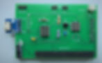
The Printed Circuit Board
The printed circuit board for the dimmer and the interface between the Rpi Zero W and the LCD was generated using KiCad. The layout is for LCDs with the standard 16 pin pinout of 2 rows of 8 pins configuration. This board, the Interface PCB, has the LCD plugged into the bottom side and the Rpi Zero W plugged into the top side. A standard female header socket is used for the Rpi (J3) but a low profile socket is used for the LCD (J2) (TE connectivity 215307-9). Both sockets are available from Mouser and Digi-Key. Power is applied to this board as well, I used a micro USB breakout board soldered at J4. The complete schematic and layout is available at Big Font Clock github.
You may use this board for a LCD without a back light, just don't populate the dimmer circuitry and LCD pins 15 and 16. The LCD contrast control, RV1, has to be installed in either case.


Enclosure
The enclosure was modified to accommodate the dimmer potentiometer on the top panel next to the mode switches. The pot is a linear taper 50 kohm 1/5 watt potentiometer. The cut out is for a TT Electronics P160KNP-0EC15A100K which is available from Mouser or Digi-Key. The modified enclosure file, enclosure backlight 200 60 45.svg, is available on the github page.
A Word About Some of the Components
Here are notes on a few of the components that are specific to the design, they are generally available through Mouser, Digi-Key and other similar sources.
Backlit 40x4 LCD: Newhaven Display makes many displays I used NHD-0440WH-ATFH-JT#. I bought mine through Digi-Key. There are also surplus displays available through MPJA.
Dimmer potentiometer: Any panel mount 50k linear taper pot may be used. The pot used here is a TT Electronics P160KNP-0EC15A100K which is available from Mouser or Digi-Key
LCD Socket J2: A low profile socket is used for the LCD, this build used a TE connectivity 215307-9 which is available at Mouser or Digi-Key
U2: IXYS CPC1510 is used for the solid state relay in a 6 pin DIP. Others could be used that are able to switch the LCD LED current.
U1: The CMOS version of the LM555 was used, this build used ICM7555. There are other CMOS versions available which should work also.
RV1: The LCD contrast pot used is a 10k linear TT Electronics 36WR10KLF. Any equivalent should work. May be sourced through Mouser or Digi-Key
Power socket: The microUSB breakout board was sourced through Amazon. Any version with similar pinout (0.1" centers) should work.
D1: Most small signal Schottky diodes should work for D1, the BAT43 was used because it was on hand.
R3: This resistor will be needed if the forward voltage of the LED back light is less than 5 volts. I recommend measuring the current used at the rated forward voltage for your display and then determine the appropriate resistance and power rating.
Setup and Operation
Power: current consumption will vary between 180 mA to 250 mA at full brightness, depending on LCD used. Current will have transitory peaks during boot. Plug a microUSB wall wart into the usb socket on the interface PC board, do not plug into the Rpi W board. The enclosure square cutouts allow the microUSB connector to pass into the enclosure, use the pair of small squares for a zip tie to anchor the cord. Use the appropriate square cutout depending on how the clock is mounted.
Setup:
The top panel is friction fitted to the case so it may be removed to connect power, adjust contrast (if needed), and to setup WiFi.
To setup WiFi, if it was not set up during loading of the python scripts, remove the top panel and remove the switch headers and brightness control header after noting connection. Then connect a monitor to the mini HDMI socket, a microUSB OTG cable to the microUSB socket nearest to the center of the Rpi Zero W board and apply power to the microUSB socket on the interface PC board. Refer to figures below. Nothing is plugged into the microUSB socket closest to the edge of the Rpi board. Attach a keyboard to the OTG cable. When the Rpi Zero W powers up you should already be logged in and at a command line.
To enter configuration menu to change the wifi parameters in 'configure network settings'
$ sudo raspi-config
You may also edit the configuration file or check to verify SSIDs and Passwords
$ sudo nano /etc/wpa_supplicant/wpa_supplicant.conf
To find available SSIDs
$ sudo iwlist wlan0 scan
To check wlan configuration
$ iwconfig or ifconfig wlan0
To see current SSID
$ iwgetid
Once the WiFi is setup then shutdown the Rpi and remove the OTG and mini HDMI cables
$ sudo shutdown -h now
Top Panel setup:
Refer to figures below
The header from the UTC switch is plugged into the UTC male 2 pin header on the interface PC board
The header from the Local switch is plugged into the Local male 2 pin header on the interface PC board
The header from the brightness control is plugged into the male 3 pin header on the interface PC board. If you want the brightness control to track opposite to its current configuration then simply flip the header at the interface PC board.
Fit the top panel back onto the case, it is a tight friction fit. Fit one end with a tab and then the opposite end.
Powerup:
Just plug in the power to the microUSB socket on the interface PC board. Once you apply power you should see the LCD light up if you rotate the brightness control. You should see a couple lines of dark squares during power up and eventually large digits. If not, the LCD contrast control on the interface PC board needs to be readjusted. When you power on, it will take a minute or two before the time and date become current.
Operation:
Rotate the brightness control to change brightness of the LCD. The brightness can be varied from full on to fully off.
The switches control the time and date readout:


